.jpg)
Return To Tips & Tricks DOWNDRAFT INLET DESIGNS
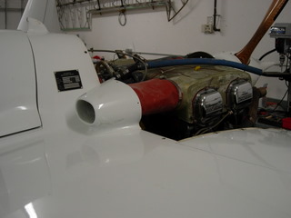
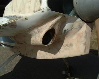
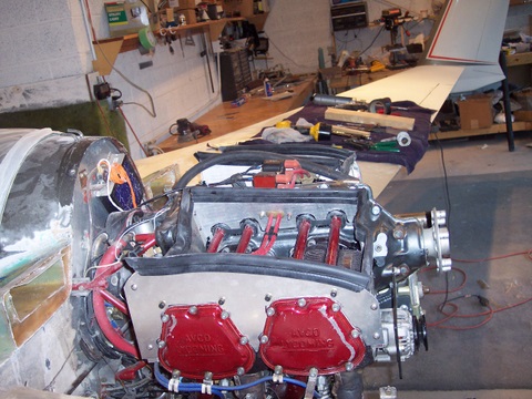
Above is the standard method of installing downdraft cooling inlets. They follow the old simple rules. Sit above the boundary layer, They have a circular opening with a radius lip around the opening. This is the standard way to grab the relative wind coming over the strake and drive it into he upper cylinder plenums. It works and its a proven method.

Your looking at fiberglass plenums over each bank of cylinders. It is important to note that there is a flexible boot connecting the rigid plenum to the inlet duct. This must be done due to engine rock and vibration. Most builders make these out of glass cloth and a high temp RTV silicone. This way custom fit sizes can be created.
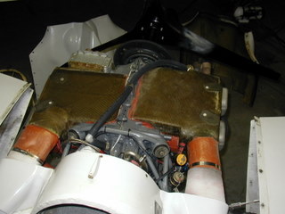
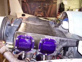
This is another example of Downdraft cooling. The plenums are a bit different as the designer wanted to also incorporate exhaust augmentation. Note the location of the oil cooler on the right rear of the engine. Inlet pressure was used for cylinder cooling and oil cooling on this design.
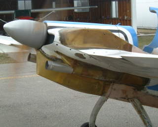
You can see the large exhaust ports allowing for the exhaust and inlet cooling air to exit the lower cowl under a negative pressure. The inlet ramp angles were just too aggressive through the transition. They were corrected after a few test flights.
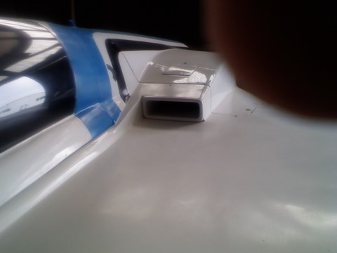
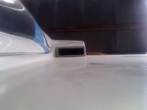
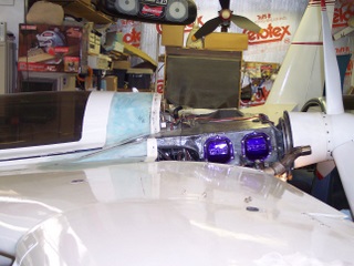
The finished product after many test flights lead to these direct ram air inlets
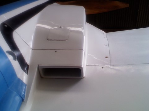
The Pilot \ Plane owner says hat his temps are with-in range and the engine cools just fine. In addition he said that he saw couple of knots of airspeed improvement with this design
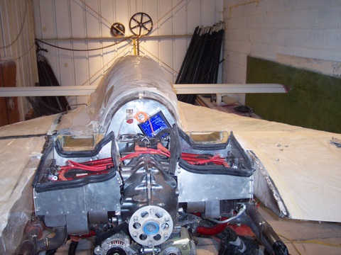
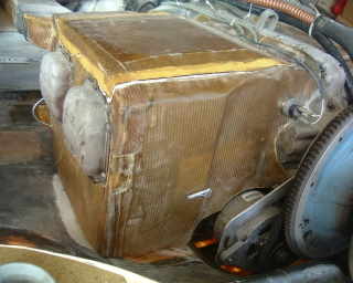
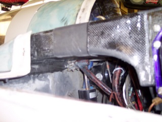
This Downdraft design used the upper cowl to seal the left and right engine cylinder plenums. In addition, the cowling deliver air through ducting built into its underside. The design was very simple. Use the upper cowling like a trunk lid to seal the plenums. Then use sunken ram air inlets to deliver the cooling air to the cowl duct and into the plenums.
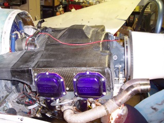
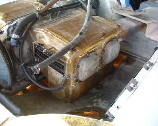
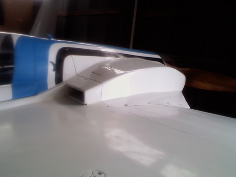
This is a very nice and compact design. The entire plenum is carbon fiber and balances the air pressure across the engine. In addition the inlets are connected with a unique slide coupler that allows for freedom of movement with little to no loss in pressure.
You can see the amount of work and thought put into this design. Very nice and done extremely clean. This builder has completed some nice carbon fiber work.